
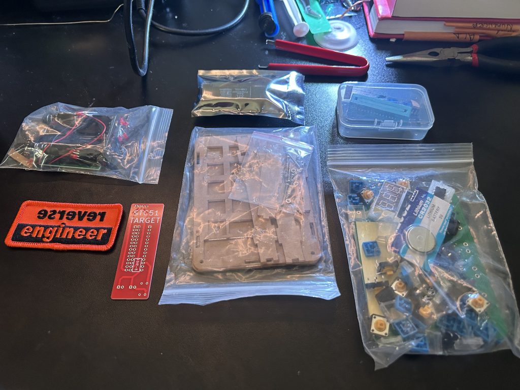
This week’s post is on another cool side project, Hackerbox 113 : “Hardcore“.
Hardcore is an intro to 8-bit microcontroller technology using modern variants of the Intel 8051, also known as “The Immortal MCU“. The 8015 is a CISC (Complex Instruction Set Computer) with separate memory spaces for program instructions and data. The goal of this project was to build a usb programmer for microcontrollers, write a simple program to program the blank 8051, and demo some applications of microcontrollers by assembling a simple LED spiral badge and a dual-mode calculator that can perform normal calculations as well as calculate resistance for electronic resistors by color band.
Behold, The Immortal Intel 8051:

After getting our parts together, the first step is to build the USB auto-programmer. This allows us to connect microcontrollers directly to our PC via a USB. We solder the socket onto the board and add a few resistors and LED’s for testing.
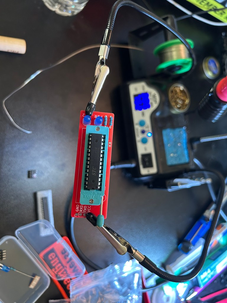
Following this, we can plug the programmer directly into our PC and write a simple program to the controller telling it to flash the LED’s and output “Hack The Planet!” to the console. There are a ton of things that we could do here, including using the chip in custom built keyboards, programming calculators, blinking LED’s and signs, and a bunch of other neat stuff.

Next we put together this simple LED badge that uses an 8 pin STC8G1K08A chip to provide instructions to the board for how to flash. This demonstrates one of the neat applications for microcontrollers! Chances are if you’ve been to a big con that does electronic badges, you’ve interacted with some similar microcontroller technology.
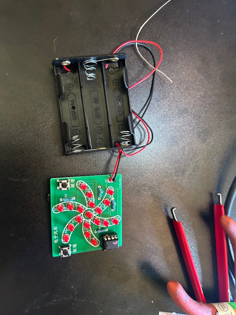
We can see in the gif below that the chip currently causes the lights to flash in a rotating pattern, with the buttons on the board being able to control the speed at which the LED’s blink.

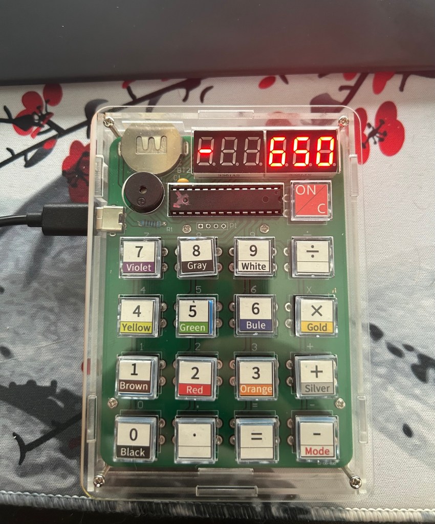
Finally, we get on to the calculator. It’s a pretty standard assembly with a socket for a battery and USB-C port for power, a small buzzer for sound, a slot for the 8051 microcontroller, a display for output and a handful of buttons for input.
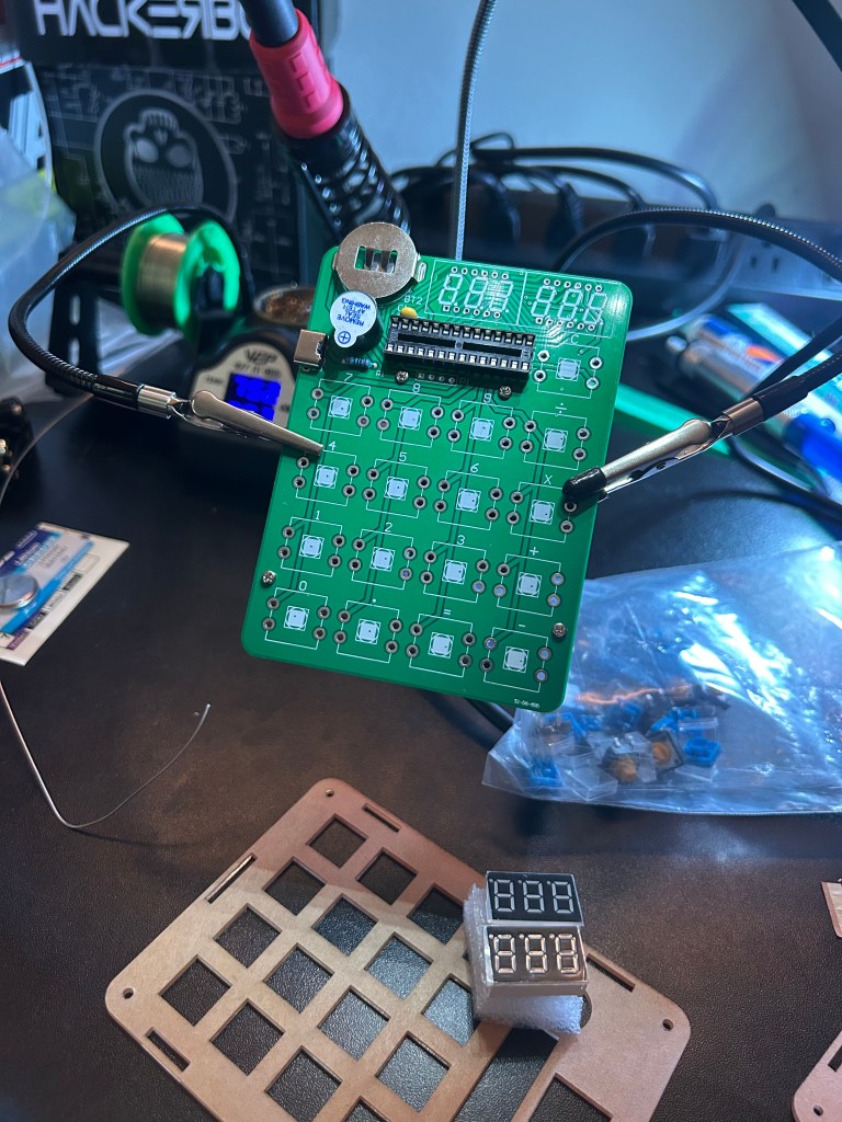
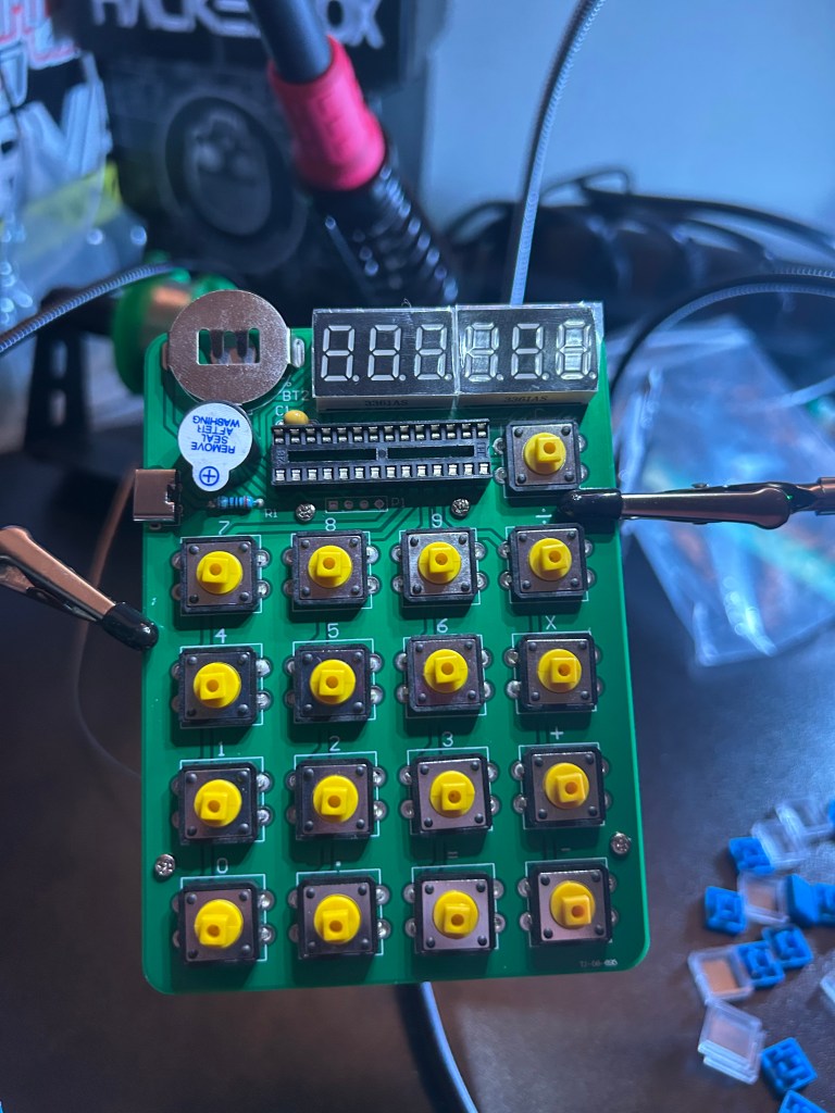
We assemble the calculator in the acrylic housing, slot the programmed 8051, and the project is complete!

The calculator is dual function; the standard function is a normal calculator with the secondary mode allowing you to add up the color bands on individual resistors to calculate their resistance value.
There were also a handful of exercises that were suggested such as:
- Programming the 8-Pin chip to change the pattern for the LED badge
- reading the calculator pins and reverse engineering the functions to change them
- making the buzzer on the calculator make weird sounds
and a bunch of other neat reverse engineering challenges that I played around with a bit but not extensively enough to write about. Overall, it was a neat project that taught be a bit more about reading and writing to Microcontrollers and small chip infrastructure. I’ll certainly be tinkering with this in my spare time for a while!
CPTS Update
In other news, I’m over 60% done with the CPTS now and my goal is to take the exam in the end of June or Beginning of July. It may be a bit later, as I want to spend a week or two re-writing my notes and methodology and doing a bunch of boxes on the HackTheBox platform to prepare. I am a bit concerned, as CPTS attempts are going to be blocked for up to 10 days starting May 18th for exam updates. Whether or not this includes new content is yet to be seen, so my study time may be pushed back a bit further to accommodate for the changes. Anyways, thanks for reading!

Leave a comment